
Since my last blog I have rendered some more graphics in the GIMP, found and converted some sound effects .WAV files and compiled almost all of the sprites. I changed the tile set to incorporate the background of the cave walls. I originally was going to make the tiles transparent and render them over the background. Then I thought, "Why?" It's just going to take more cycles to do both. I combined them both. This was we can stack blast the tiles from a buffer and directly onto the playing screen. It will cost less cycles then drawing transparent tiles over a blank background. I have provided an image of the new tile set below so you can compare to the one I showed in a previous blog. The background colors of dark gray and black may still change. I haven't decided yet.

Back to the subject at hand... compiling sprites! As I mentioned before there are some sprite compiling programs out there. One I have used before is Glen Hewlett's. It's very very good and well designed. It, like any other compiler, still needs manual modification in order to optimize the code for the shortest amount of cycles. Since I have to extract each sprite from my graphics editor, save it as a bitmap, then process it through the compiler and then hand edit I decided to just stick with my current very manual method of compiling sprites. It's hard to program an analysis of the image that accounts for EVERY scenario to make the compiling more efficient and optimized. As I just stated my process is very manual and involves a lot of time. It is definitely the least exciting part of our game development. With that said there are several other methods and I am not claiming mine to be the best or even closely the best. It is simply the method I use to get the results I desire.
Why compile sprites? The CoCo 3 did not come with hardware sprite support. Which some people feel is a downfall, but I beg to differ. If you look at some other systems from around the same era that DID support hardware sprites they were VERY limited. Size and color depth mainly were the limitations there. So I like the fact that you CAN and SHOULD compile sprites on the Coco 3.
Another method is to store the images of your sprites in a buffer in memory and then copy to the screen as needed. This is what Color BASIC does. The downfalls are that it's slow and even slower if you involve transparencies. Let's be honest, nobody wants to see a game with those random colored dots or rectangles around the sprites. Another downside of buffered sprites is you typically have to use one palette slot (0 is easiest) to signify a transparent pixel. It is okay in many situations and if your game is limited graphically, by all means use a buffer because you will save yourself a lot of time. I on the other hand make very graphics intensive video games. It's just what I like to do. Writing a set of instructions to render those graphics to the screen is the fastest method, but consumes more memory. There's always a trade-off somewhere as you will learn when we talk sound.
 So what is a compiled sprite? Quite simply it is a set of assembly instructions to render the graphics to the screen. That's it and that is why it consumes more memory, but executes faster. There are many different strategies to consider when compiling sprites as well. Those strategies are decided on a per sprite basis or even a per LINE basis. Sometimes you want to load a value (LD) directly into an accumulator (A or B) or address (X,Y) register. And sometimes you will "stack blast". Other times you will work left to right, right to left or even center to left and then back right. You'll likely not even progress in line order. It all depends on what I refer to the HEX map.
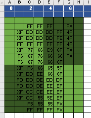
Take the image below of the DL2 dude standing still. I take that right out of my graphic editor and byte by byte, line by line create a "HEX map" of the image in Excel. You can see the HEX map of this guy right here to your right. Let me explain the HEX map in a bit more detail.
 I chose Excel because I can easily manipulate the size of each cell, color each cell accordingly (more on that in a moment), and also set the very top row to NOT scroll. This is important so that I can scroll up and down as I do different sprites, but those values never move.
The top bar contains the offset of the sprite in relation to the current screen address I am working. 0, for example, is that actual address. So let's say my screen is at $4000 (16,384 decimal). If I write instruction STD ,U and register U is loaded with the value #$4000 the byte from register D would be stored at address $4000. You'll see that I skip the numbering of the next byte and go to 2,4,6 and so on as needed. Those are offsets from the original starting address. And I skip the odd numbers just because it is less confusing to the eye. With that I would STD 2,U and that would write the byte from D to address $4002 which is 2 away from U's current value of $4000. Hopefully I made that easy to understand.
As you can see in the image of the HEX map I typically break the image map up into 4 equal sections and alternate colors. It just visually makes it easier. Trust me your eyes can become very blurred when doing this laborious task! Visual aids are key. At least for me.
Once I've established the address offsets in the top row and visually divided my sprite block up I will then go pixel by pixel, line by line through my image and write the hexadecimal values of each byte onto the grid. Each byte is 2 pixels, at least in the graphics mode I use. DL2 will be 256x200x16 graphics resolution. So each cell contains the hex value for each byte of the sprite. The X's mark where I will have to mix the sprite with the screen to create transparency. As a hint, make the edge color of your sprite in palette slot 15 or F as this reduces the amount of steps necessary to create a transparency. This was a trick I learned from my good buddy Glen Hewlett's blog. Glen's blog can be found here.
Once I have my hex map all setup, and I usually do multiple sprites on one Excel sheet, I am ready to start programming the compiling. I have a .asm file I continuously use to compile my sprites. You have to set up the palette, the screen mode and ALL of that stuff before you can compile IF you want to compile and run to visually verify your progress. My compiler .asm file puts the Coco 3 into a 128x111 graphics mode. The images are bigger and chunkier so I can see the details and easily identify mistakes. I also will typically CLS my screen with a striped pattern so I can verify my transparencies are working. I will provide screen shots along the way and I will also attach a copy of the .asm file for you.
As I compile I will generally compile and check about every 2-4 lines. Sometimes more if my confidence level is high! As I go I will highlight in Excel the bytes I have completed. If I check and there are errors I will go back to Excel and highlight in red the line where the error occurred. This helps me isolate that line of the HEX map and identify the changes I need to make in the code. Inside the code editor I will group together the instructions for one line and then provide a space between each group. This way if there are errors I can easily count lines.
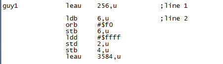
Now let's get into the specifics of compiling THIS sprite. You'll notice the top and bottom lines of the sprite contain a lot of "FF." Which is black in my case. As I mentioned earlier, making your sprite edges be F makes transparency mixing take less steps. In this case I will like do the top and bottom lines first and then go back up to continue from the second line. I will do this as it will reduce the amount of times I load the same values into registers. Everything takes time! It's your job to reduce that time as best you can. You also don't want to load a value once and jump around to the various points it's needed because this will cost even more cycles.
So I'll start with this:
LEAU 256,U ;skip the first line as there is nothing there. my screen width will be 256 bytes
LDB 6,U ;load B with the value from U+6
ORB #$F0 ;OR B to mix the sprite. $F is the value from the sprites edge, 0 will become
;that nybbles value from the screen. If the screen byte is $ED it will become $FD
STB 6,u ;store the modified screen byte back at U+6
We'll take care of that one transparency first and then move onto this:
LDD #$FFFF ;load the value (value is indicated by #) of $FFFF into register D.
STD 2,U ;I use U as my address pointer so I can stack blast if necessary
;this instruction stores $FFFF at U+2 essentially
STB 4,U ;Store the LSB of register D (register B, registers A+B=D) at U+4
LEAU 3584,U ;This adds 3584 to the value in U to "move" in this case to the bottom line of the sprite
;why 3584? My screen in DL2 will be set up to use the hardware scrolling mode
;which enables a 256 byte wide virtual screen which you can scroll.
;the bottom line is 14 lines down and the screen is 256 bytes wide
;256x14=3584
This takes care of the first and second lines. I chose to do the transparency first because then D is loaded with $FFFF upon exit to the next line. This way we can start the next line with $FFFF without reloading the register. Keep your eyes peeled for these opportunities as you go. It will save you precious cycles! Now I mark off what I've done in Excel and move on.

CODE:
I don't really see any opportunities where stack blasting is going to be more efficient for this particular sprite so I will address that later.
As I coded I ran a sample of my progress in VCC by compiling my code using LWASM and the windows command prompt. I then drag and drop my program into the VCC emulator icon and it loads automatically. I notice in my run that there as an error at the 13th line of the sprite. I highlighted the error in red in Excel and went back into the code to fix the problem. You can see below that one pixel that should be black is dark gray.


What's up with all the stripes man? I have a loop at the end of my compiler program that cycles through all the colors in the border really quickly. That signals that I'm not stuck in a loop somewhere and that the program is functioning as it should. The stripes on the screen help me verify my transparencies are working properly.
After making the correction I finish the rest of the instructions and I now have my finished product!


As promised I have attached the code to this blog for your review. I tried to comment as best I can. I'm not really a commenter normally, but since I am sharing it's important you know what each line does. There are probably things that other programmers will notice that could be better. That's fine. I know that, but please don't criticize. I hope this entry has been informative and helpful! Enjoy picking apart my code.
Next time I will talk more about what my plan is with the tiles. Thanks again for reading!
Copy and paste this into Notepad or another .txt editor:
opt 6809
org $e00 ;program origin address (EXEC &HE00)
*disable interrupts
start orcc #$50
fast lds #$059f ;move stack to new place
sta $ffd9 ;high speed! CC3
sta $ffd7
;set all palettes black
ldu #black ;load address of label "black" into U
tst $ff02 ;wait for VSYNC
vsync0 tst $ff03
bpl vsync0
jsr setpal ;jump to set pallette sub routine
lda #$68 ;set up screen for graphics CC3
sta $ff90 ;mmu's set task1 CC3, $ff90 GIME init. register
ldd #$8272 ;64x112 screen byte resolution x16 colors
std $ff98 ;$ff98/ $ff99 are video mode/ resolution
;registers
ldd #$3233 ;move pages $32 and $33 into MMU space
std $ffa2 ;$ffa2 sets page at $4000
;$ffa3 sets page at $6000
;clear the screen with my chosen patterm
ldx #$4000 ;load X with screen start address
ldd #$0120 ;load D with my CLS value
cls std ,x++ ;store D @ screen address X
cmpx #$7fff ;check if we're at the bottom
blo cls ;clear more if we're not
ldd #$3031 ;move pages $30 and $31
std $ffa2 ;into $4000 and $6000
ldx #$4000 ;same as CLS above
ldd #$6789
cls0 std ,x++
cmpx #$7fff
blo cls0
ldd #$c000 ;point vertical offset register to page start at $30
std $ff9d ;page number * 4 $30*4=$c0
;$ff9e is like a "shift" register... so we leave it
;0 for now
;set palette to full 16 color RGB
palettergb ldu #rgb ;same as setting palette black above
tst $ff02
vsync2 tst $ff03
bpl vsync2
jsr setpal
lda #$80 ;enable HVEN
sta $ff9f
ldu #$4000 ;point U very top left of screen
jsr guy1 ;jump to sprite compiling
looper inc $ff9a ;increase the border color infinitely
jmp looper
opt cd ;enable cycle counting for output file
opt ct ;enable cycle count totalling
guy1 leau 256,u ;line 1
ldb 6,u ;line 2
orb #$f0
stb 6,u
ldd #$ffff
std 2,u
stb 4,u
leau 3584,u
std 2,u ;line 16
ldb 5,u
orb #$f0
std 4,u
leau -2816,u
ldb #$4f ;line 5
std 5,u
ldb #$ff
std 1,u
std 3,u
leau -512,u
ldb #$4f ;line 3
std 5,u
ldb #$dd
lda 1,u
ora #$0f
std 1,u
lda #$dd
std 3,u
leau 256,u
std 3,u ;line 4
lda 1,u
ora #$0f
std 1,u
ldd #$fe4f
std 5,u
leau 512,u
lda 1,u ;line 6
ldb 6,u
ora #$0f
orb #$f0
sta 1,u
stb 6,u
ldd #$c96f
std 4,u
ldd #$7766
std 2,u
leau 256,u
ldx #$f667 ;line 7
stx 1,u
lda 6,u
ora #$f0
sta 6,u
stb 5,u
lda #$76
std 3,u
leau 256,u
stx 1,u ;line8
std 3,u
lda #$6f
sta 5,u
leau 256,u
lda 1,u ;line 9
ora #$0f
sta 1,u
ldd #$f666
std 2,u
ldd #$655f
std 4,u
leau 256,u
lda 1,u ;line 10
ora #$0f
sta 1,u
ldd #$ddee
std 2,u
ldd #$666f
std 4,u
leau 256,u
ldx #$fddd ;line 11
lda #$df
stx 1,u
sta 5,u
ldd #$deed
std 3,u
leau 256,u
stx 1,u ;line 12
ldb #$ee
std 3,u
ldb #$ef
stb 5,u
leau 256,u
lda #$ee ;line 13
std 4,u
lda 1,u
ora #$0f
sta 1,u
ldd #$ccce
std 2,u
leau 256,u
ldb #$55 ;line 14
std 2,u
ldd #$5eef
std 4,u
lda 1,u
ora #$0f
sta 1,u
leau 256,u
lda 5,u ;line 15
ora #$f0
sta 5,u
ldd #$f555
std 2,u
stb 4,u
rts
black fcb 0,0,0,0,0,0,0,0,0,0,0,0,0,0,0,0 ;data for black
rgb fcb 3,24,27,48,54,34,52,4,32,11,5,40,63,56,7,0 ;data for RGB
setpal ldx #$ffb0 ;point X to palette registers
repal lda ,u+ ;load value from U pointer address into A
sta ,x+ ;store A where X points
cmpx #$ffc0 ;check if at end
blo repal ;do again if not
rts ;return to where we came from
end start ;end of program
No comments:
Post a Comment